Introduction
UP-PCM-275-2P-1 is for installation at LPZ0-1 or higher,protecting low voltage equipment from surge. Applied in modular SPD Class II(Class C)for TN power supply system.Designed according to IEC 61643-11;EN 61643-11
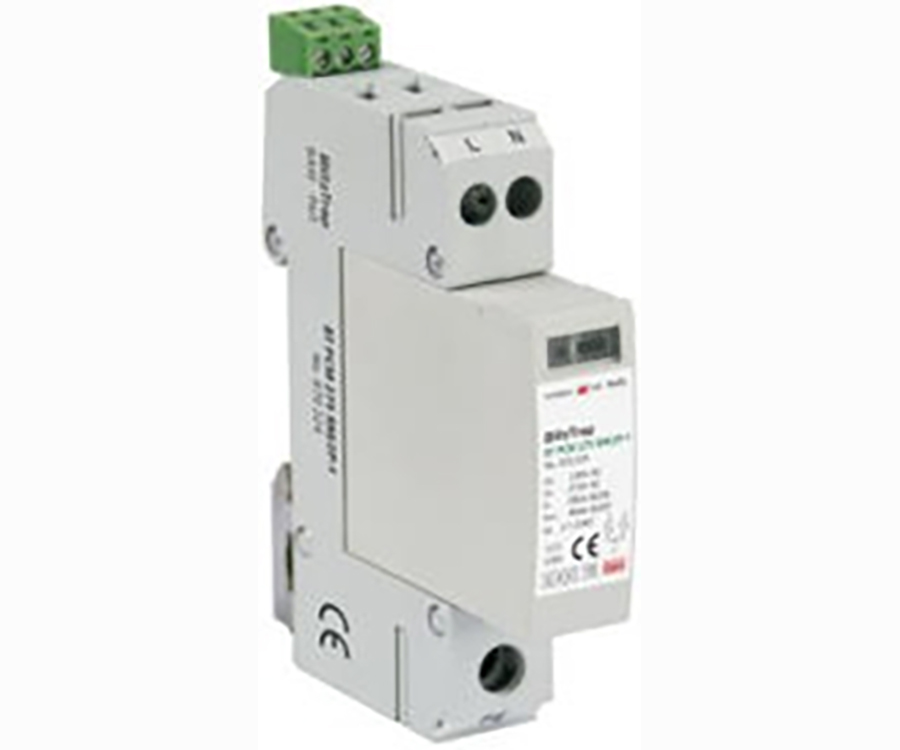
Features
Modular SPD for single-phase TN system
Pluggable module,easy for installation and maintenace
High discharge capacity,quick response
Double thermal disconnector device,providing more reliable protection
Multifunctional terminal for connecting conductors and busbars
Windows will change red when fault and also provide remote alarm control at the same time.
Application
UP-PCM-275-2P-1 is used in TN system,protecting devices or equipment downstream.
Application Enviroment
Temperature: -40~80
Relative humidity: <95%
Installation Instruction
According to lighting protection zones concept,for installation at LPZ 0-1 or higher, This surge protective device is usually installed in distribution-box or feeder bus of UPS,protecting devices or equipment downstream.
Fuse must be installed at the upstream of the SPD or the linghting arrester to make sure that the protected system has double protection. The value of the fuse used in a SPD system should be conformed to:
The value of FUSE should not be larger than the max withstand capacity of the SPD& 39;s backup fuse value.
Under the status of the max. current in the power supply& close loop circuit available current,the fuse should be able to disconnect when overloaded or short-circuited
Take 1&2 into consideration,the fuse should be as large as possible to allow the maximum surge discharge of SPD.
Installation steps
Check the product for integrity of the package; makesure the product window indicates green.
Mount the SPD on the 35mm DIN rail.
Connect conductors,the cross-section area of cable mustbe larger than 6mm& 39;.The withstand voltage value of cableis not smaller than AC500V;ensure wining reliable.
If need remote alarm,it should be connected signal inesto remote signal terminal 2 and 3(When normal,1 and 3close,2 and 3 open; when fautt,the state is reversed)
After above, switch on the power supply and tur on thecircuit breaker,if the SPD& 39;s window indicates green,thisindicates the unrt is operating nomally
Regularly inspect the operating status,especially after lighting. Once the fuse upstream breaks, or the SPD& 39;s window indicates red,electrician should check/replace the SPD.
Installation diagram:

Basic circuit diagram